Technical Guide to the TAD-2 Wind Tunnel
2. TAD-2 Wind Tunnel
3. Types of Wind Tunnel Tests
3.1 Six Component Force Testing
In these experiments, a model is mounted on a strip support of external six-component strain balance 6KETB (Fig. 3.1). Aerodynamic loadings are measured at different angles-of-attack (sideslip) and at preset air velocity. The bases of the support are commonly used in former USSR wind tunnels and are as follows:
Lateral base lz: 400, 600, 800, 1000, 1200, and 1500 mm;
Longitudinal base lx: -400, 400, 600, 750, and 900 mm.
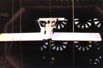
Figure 3.1 Ultralight Airplane Model on the Support of Six-component Strain Balance
3.2 Quasi-static Modeling of Object Separation
The object being tested is mounted on six-component balance and in the test section a substantial element of a flight vehicle (for instance, airplane) is installed, from which the object is being separated. The separation is modeled by appropriate displacement of this element relative to object. The measurements of all six components of aerodynamic loading on the object are performed at different angles-of-attack (sideslip).
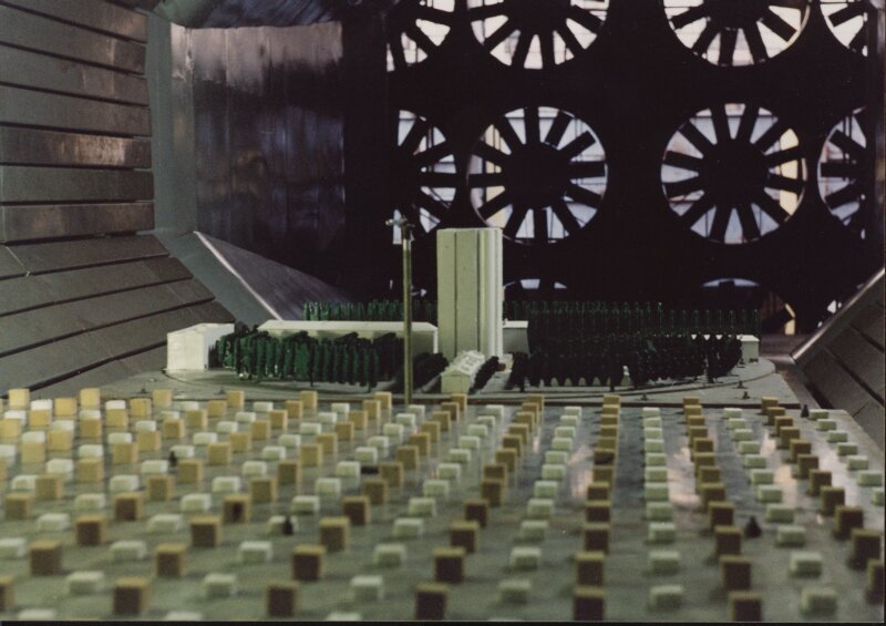
3.3 Dynamically Similar Models Testing
Dynamically similar models are mounted on six-component balance or on the turntable, which is the element of the lower wall of the test section. For the tests the model is equipped with internal strain gauge transducers or other devices, sensitive to kinematics of oscillating elements of the object (Fig. 3.2).
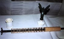
Figure 3.2 Dynamically Similar Model of Independence of Ukraine Monument Column
3.4 Wind Power Units Testing
Wind power units are mounted on the turntable and equipped with the speed-of-rotation transducer and braking system with the torque sensor (Fig. 3.3).
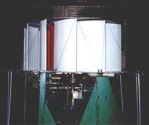
Figure 3.3 Wind Engine Installation
3.5 Static Pressure Distribution Testing
The investigation of static pressure distribution on the surface of objects is performed with remotely controlled scan valve (up to 420 points, up to 200 measurements per second), mounted in internal volume of the object (Fig.3.4).
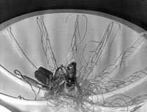
Figure 3.4 Scan Valve in the Internal Volume of Aerostatic Carrier Model
The subsystem of pressure distribution experiment provides measuring of instantaneous pressure values in drain ports on the model surface allowing to research models in transient condition (Figure 3.5).
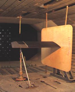
Figure 3.5 Photo of wing compartment model at forced vibrations device during researches of instantaneous pressure distribution on the model surface
Maximal amount of informative channels and, accordingly, pressure sensors simultaneously involved in experiment is 256 (Figure 3.6). The amount of drain points can be increased at customer request. Range of the measured values of air pressure by every МРХV5004G type sensor is within the 400 mm of water at a frequency pulsation to 1000 hertz. Interface board operates within the environment of the integrated package of the graphic programming LabVIEW.
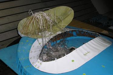
Figure 3.6 Photo of stadium model in Vilnius during mounting of awning crest with the pressure distribution system
Method of aerodynamic experimental researches of influencing of high-rise houses on the pressure distribution in outcomes of air pits of existent alongside low dwelling-houses was developed on the base of wind tunnels TAD-2 and UTAD-2 NAU (Figure 3.7).
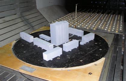
Figure 3.7 Photo of development lot model at researches of aerodynamic operation conditions of ventilation systems of houses round a new tall house in Kalininskiy district of Donetsk
In the case of exposure of the negative influencing of new building operation of ventilation systems of adjoining houses structural measures on the improvement of operation conditions of ventilation are developed and experimentally checked up (Figure 3.8). Solution of the mention problem is offered as the patent on useful model № 40868, Ukraine, 27.04.2009 «Pavlovskiy’ complex for defence of exhausts of gas remove canals of low dwelling-houses located very close to many-storied one».
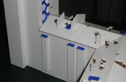
Figure 3.8 Photo of roof part of model of house № 90 at Artema street in Donetsk recommended for application
3.6 Full-Scale Power Plants Testing of Ultra-Light Airplanes
Test rig for full-scale power plants testing permits obtaining the complete set of characteristics of piston engines with airscrews (both propeller and tractor) up to 1.8 meters in diameter (Fig. 3.5). Maximum thrust 1250 N, max torque 250 Nm.
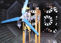
Figure 3.9 Test Rig for Full-scale Power Plants Testing of Ultra-light Airplanes
3.7 Icing Conditions Modeling
Climatic conditions in Kyiv give an opportunity to investigate natural icing processes of objects during three winter months (night time is preferable). For this purposes TAD-2 wind tunnel is equipped with spray system capable to create an aerosol cloud in the test section with droplet diameter range of 5 to 100 micrometers. The desalinated water is used obtained from the ion-exchange resin system. The object can be mounted on a separate test rig that includes two-component strain gauge, or on the six-component strain balance (Fig. 3.10). This permits measuring of aerodynamic loading directly with real ice accretion and not with the plastic copy, used in most wind tunnels.
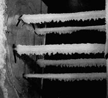
Figure 3.10 Icing Investigations of the So-called "Split Phase" Wires of High-voltage Power Lines on Six-component Strain Balance
3.8 Heavy Rain Conditions Modeling
Spray system for heavy rain modeling creates in the test section a two-phase flow with droplet size from 0.5 to 8 mm and liquid water content up to 80 g/m3 that corresponds to rainfall rate of 2000 mm per hour. The influence of heavy rain conditions is investigated on aerodynamic characteristics of airplanes.
3.9 Visibility Investigation through Windshields in Precipitation Conditions and Means for Its Improvement
A full-scale windshield is installed in the test section together with means for visibility improvement and elements of the vehicle that makes the flow round it similar to real. Using spray systems, described in previous subsections, heavy rain or icing conditions are created. The investigation of visibility characteristics are performed using video camera(s), installed in position(s) of real pilot (driver) eye(s).
3.10 Hinge Moments Measuring
Investigations are usually performed on half-models in order to increase model scale, which assure the more valid data to be obtained. For these tests the model is equipped with internal strain gauge transducers sensitive to hinge moment of specific control surface. The half-model is mounted to the side strut of the angle-of-attack alteration mechanism. The last is installed on the truss, located outside the flow. The cut side of the half-model is adjacent to the special shield.
Investigations are possible in modeled heavy rain or icing conditions.
3.11 Certification of Anemometers and Wind Direction Meters
Testing and certification of means for wind velocity and wind direction measurment, pitot probes, five-hole and, six-hole probes; etc are performed with the named unit, mounted on the turntable. The flow velocity ranges from 2 to 41 m/sec, relative flow direction varies in range of 0...360 deg. The wind tunnels TAD-2 and UTAD-2 NAU are admitted to application as workings standards according to All-Union state standard 8.542-86.
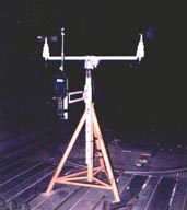
Fugure 3.11 Anemorhumbometer "Marc-60" in TAD-2 Test Section
The investigation of flow round the buildings is performed
with modeling of ground turbulent boundary layer. For this
the system of turbulence stimulators are developed and mounted (Fig. 3.12).
Both visual investigations of flow and pressure distribution
measurements in the reference points of building surfaces
are performed.

Figure 3.12 The model of microdistrict with the turbulence
stimulation system.
| 
 Ukr
Ukr