Technical Guide to the TAD-2 Wind Tunnel
6. Requirements to Models
6.1 Model Mounting on Six Component Strain Balance
6KETV balance has ф universal base set commonly used in almost all large wind tunnels of former USSR and CIS:
Lateral base: : 400, 600, 800, 1000, 1200 та 1500 mm;
Longitudinal base : -400, 400, 600, 750 та 900 mm.
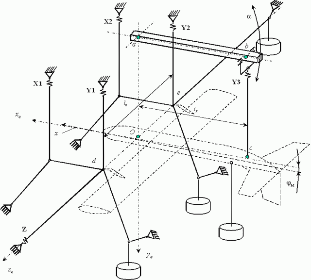
Cinematic scheme of strip support is shown in Fig. 6.1. Any combination of lateral and longitudinal bases is possible.
Figure 6.1 Cinematic Scheme of 6KETV Strip Support Balance
(Click on image for enlarged view.)
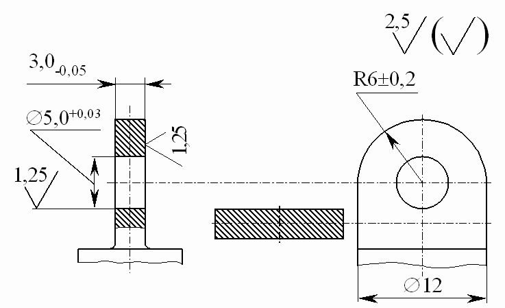
The model is installed on the balance with brackets, mounting dimensions of which are shown in Fig. 6.2 and 6.3. The model should have two front brackets to install it into "d" and "e" joints and upper and lower aft brackets, the upper one to be installed into "с" joint to hold model on the balance, and lower one into "f" joint to accommodate counterweight with damper. Longitudinal and lateral base sizes should be observed with deviation less than 0.5 mm. "f" joint position is more or less arbitrary. All the brackets are to be fabricated from the material with yield point not less than 650 MPa (65 kg/mm2).
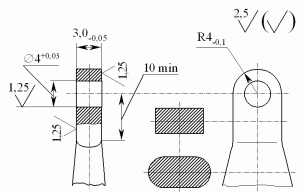
Figure 6.2 Mounting Dimensions of Front Bracket

Figure 6.3 Mounting Dimensions of Aft Bracket
6.2 Model Strength
The model installed on the brackets is to withstand overload at least two times greater than expected in wind tunnel run. Loads have to be distributed by model surface according to that in real airflow. Models, developed and manufactured by the customer, undergo strength test without exception in presence of Aerodynamic Research Center representative and the appropriate certificate is executed.
6.3 Additional Requirements and Recommendations
1. The model must be supplied with log, where all necessary data are designated.
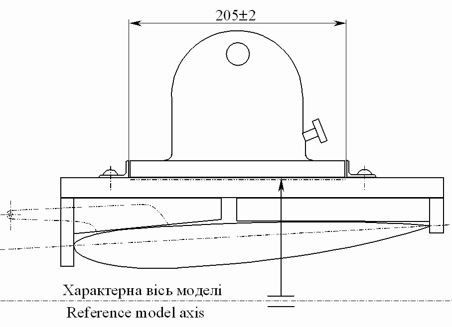
2. The model must be supplied with the reference block (Fig. 6.4), which can be mounted on the wing or other reference surface in a uniform way and fixed tightly. Upper block surface must be flat (within 0.01 mm) and must be not less than 205 by 75 mm. This surface serves for optical inclinometer mounting. Flat surface must be parallel to the reference model line or have a known angle with it, which is indicated in model log. Exception can be done for axisymmetrical objects, which have cylindrical portion 250 mm or longer and cylinder axis is the reference axis of an object. Another exception is possible if flat surface that satisfies requirements mentioned is a part of a model itself.
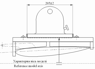
Figure 6.4 A Sketch of Reference Block for Optical Inclinometer Mounting
| 
 Ukr
Ukr